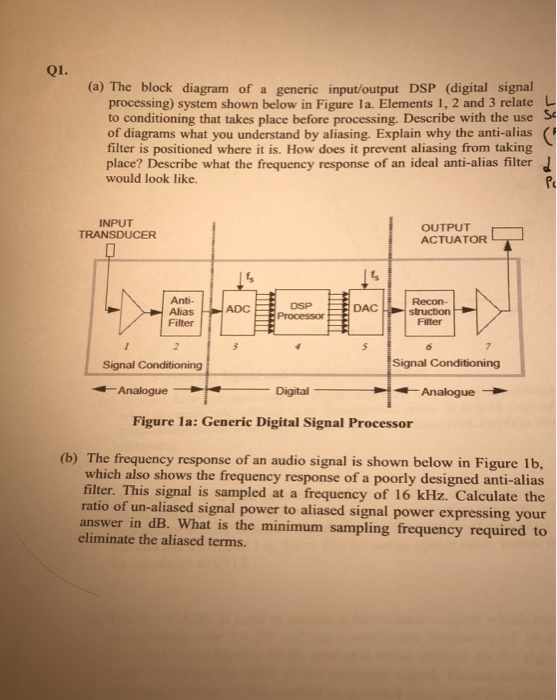
 (a) The block diagram of a generic input/output DSP (digital signal processing) system shown below in Figure 1a. Elements 1,2 and 3 relate to conditioning that takes place before processing. Describe with the use of diagrams what you understand by aliasing. Explain why the anti-alias filter is positioned where it is. How does
OR
OR