Consider the circuit in Figure 1. It is a 4-bit synchronouscounter which uses four T-type flip-flops. The counter increments itsvalue on each positive edge of the clock signal if the Enablesignal is high. The counter is reset to 0 on the next positiveclock edge if the synchronous Clear input is low.
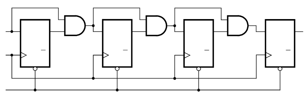
Figure 1: A 4-bit counter.
Write a VHDL file that defines a 4-bit counter by using thestructure depicted in Figure 1. Your code should include a Tflip-flop entity that is instantiated four times to create thecounter. Compile the circuit. How many logic elements (LEs) areused to implement your
OR
OR