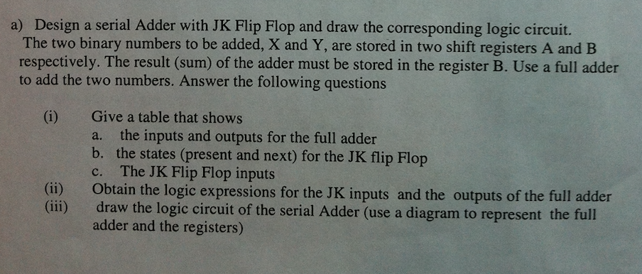
Design a serial Adder with JK Flip Flop and draw the corresponding logic circuit. The two binary numbers to be added, X and Y, are stored in two shift registers A and B respectively. The result (sum) of the adder must be stored in the register B. Use a full adder to add the two numbers. Answer the following questions a) Give a table that shows a. the inputs and outputs for the
OR
OR
